Mechanical Seal Failure or Bearing Failure? How to Diagnose Fast
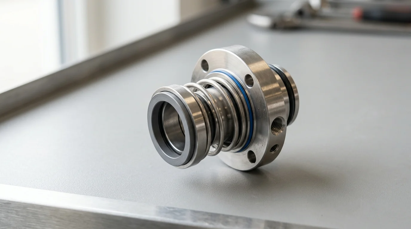
When a centrifugal pump runs hot, vibrates, or begins leaking, the obvious suspect is not always the true root cause. A damaged bearing can push the shaft beyond the tight limits a mechanical seal can tolerate, while a leaking seal can contaminate lubrication and destroy bearings within hours. In facilities where unplanned downtime can cost tens of thousands of dollars per hour, fast diagnosis is not guesswork—it is a reliability discipline. This guide explains how to separate seal-related symptoms from bearing-related symptoms using practical evidence such as temperature, vibration, shaft runout, leakage patterns, and oil condition, so maintenance teams can repair the initiating fault instead of repeating the same teardown.
Mechanical Seal Failure vs Bearing Failure
In rotating equipment such as centrifugal pumps, compressors, and industrial agitators, the boundary between a mechanical seal failure and a bearing failure is frequently blurred by overlapping symptoms. Both components share the same physical shaft and operate in close proximity, meaning the degradation of one often accelerates the destruction of the other. For reliability engineers and maintenance technicians, distinguishing the root cause of excessive heat, abnormal vibration, or erratic power consumption is a critical diagnostic challenge.
Misdiagnosing these failures leads to ineffective repairs, repeated teardowns, and extended production outages. In heavy process industries like petrochemical refining or pulp and paper manufacturing, unscheduled downtime can incur costs ranging from $10,000 to over $50,000 per hour. Consequently, establishing a rigorous, evidence-based diagnostic protocol is essential for isolating the failing component before catastrophic secondary damage occurs.
Why fast diagnosis protects uptime
The primary objective of rapid diagnosis is to prevent the cascading failure mechanisms inherent to rotating machinery. A mechanical seal and a bearing exist in a symbiotic mechanical relationship; the bearing must maintain rotor stability to allow the seal faces to track properly, while the mechanical seal must contain the process fluid to prevent contamination of the bearing lubrication system.
When a bearing begins to spall or lose its internal clearances, it permits excessive shaft deflection. If radial runout exceeds typical mechanical seal tolerances—often as tight as 0.002 inches (0.05 mm)—the dynamic O-rings will fret, and the rigid seal faces will chip or separate, leading to immediate fluid leakage. Conversely, a primary mechanical seal failure that sprays corrosive or abrasive process fluid into the bearing housing will rapidly degrade the lubricating oil’s viscosity, causing the bearings to seize within hours. Identifying the initiating component halts this destructive loop.
When early symptoms require controlled troubleshooting
Not all symptoms demand an immediate emergency shutdown; some require controlled, systematic troubleshooting while the equipment remains online. Early-stage degradation often presents as subtle shifts in condition monitoring data rather than overt physical damage. When sensors detect a baseline deviation, diagnostic teams must initiate a structured investigation without unnecessarily interrupting the process.
For example, a gradual increase in bearing housing temperature approaching 180°F (82°C) or a shift in overall vibration velocity exceeding 0.15 in/s RMS indicates an emerging anomaly. At this stage, technicians can safely perform high-resolution vibration analysis, thermography, and oil sampling. Controlled troubleshooting allows the facility to secure replacement parts, schedule a deliberate outage, and prepare the necessary lock-out/tag-out (LOTO) procedures, thereby transforming an unpredictable failure into a managed maintenance event.
Failure Boundaries and Key Differences
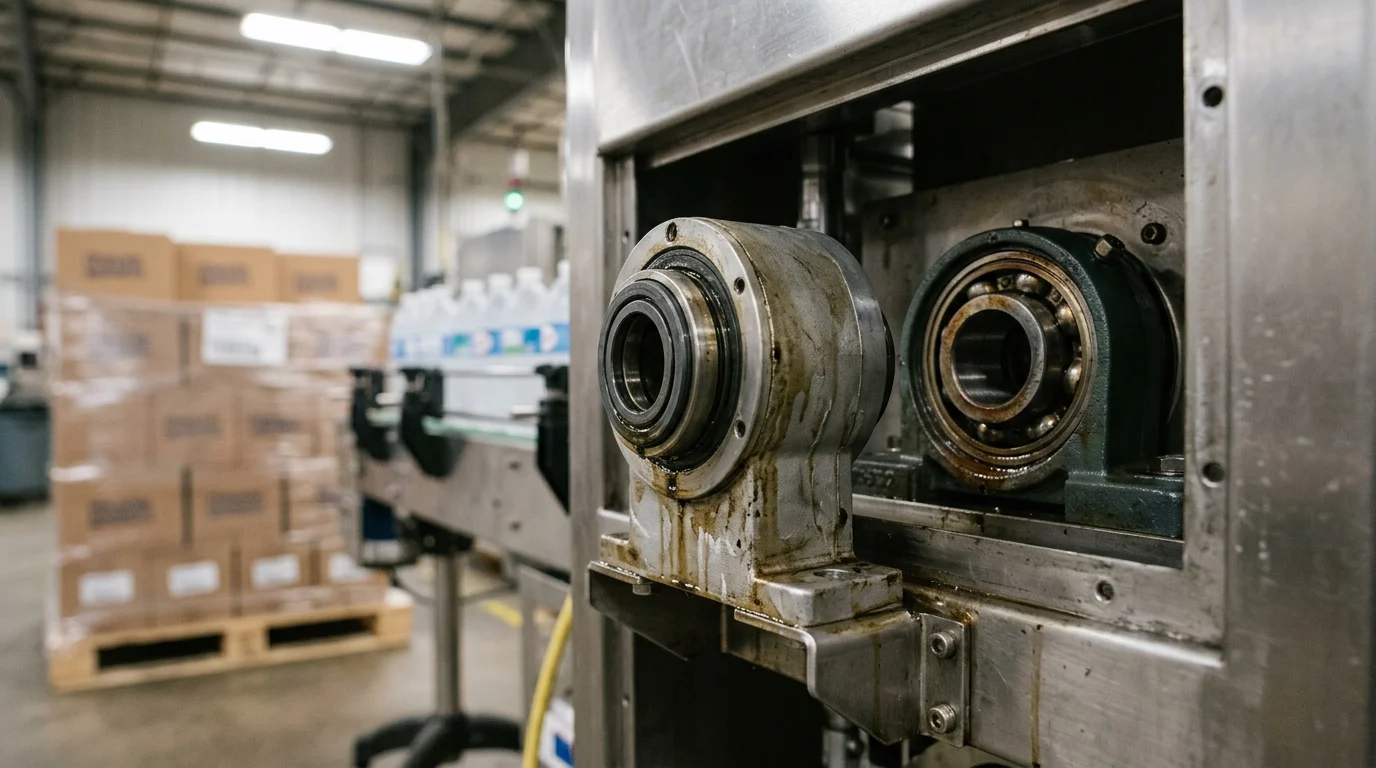
To accurately diagnose equipment distress, technicians must first understand the distinct operational boundaries and functional requirements of both the mechanical seal and the bearing assembly. While they operate on the same rotating assembly, their design parameters, failure thresholds, and physical reactions to systemic stress differ significantly.
A mechanical seal is a precision fluid-containment device relying on microscopic clearances, whereas a bearing is a load-transmission component designed to handle heavy mechanical forces. Recognizing where fluid dynamics end and structural mechanics begin is the foundation of accurate field diagnostics.
What a mechanical seal protects
A mechanical seal serves as the primary barrier between the internal process fluid and the external atmosphere. Its core function is achieved through two highly polished seal faces—one stationary and one rotating—pressed together by spring tension and hydraulic pressure. These faces do not run completely dry; they rely on a microscopic fluid film, typically measuring between 1 and 3 microns in thickness, to provide lubrication and cooling.
Because the mechanical seal operates with such minute clearances, it is highly sensitive to fluid conditions. It protects the environment from hazardous chemical releases and shields the process from atmospheric contamination. However, its effectiveness is entirely dependent on the process fluid remaining within specific temperature, pressure, and vapor-margin parameters. When a mechanical seal fails, the primary consequence is a loss of containment, which manifests as visible leakage, vapor clouds, or a drop in barrier fluid pressure in dual-seal configurations.
What a bearing supports
Bearings are designed to support the rotating shaft, managing both radial loads (perpendicular to the shaft) and axial thrust loads (parallel to the shaft). By maintaining the rotor in its precise geometric center, bearings ensure that impellers do not contact casings and that mechanical seal faces remain aligned. Industrial rolling element bearings are engineered for a specific L10 fatigue life, frequently calculated between 25,000 and 50,000 operating hours under ideal lubrication and load conditions.
Unlike seals, bearings are not directly exposed to the process fluid. Their environment consists of a housing filled with lubricating oil or grease. A bearing’s health depends on maintaining a continuous elastohydrodynamic lubrication film between the rolling elements and the raceways. When a bearing fails, it loses its ability to constrain the shaft, leading to increased mechanical friction, rapid heat generation, and high-amplitude vibration as the internal clearances expand beyond design limits.
Mechanical seal vs bearing failure signs
Differentiating between the physical signs of seal and bearing failure requires correlating visual, auditory, and thermal evidence. Because the components are housed near each other, heat and noise can easily transfer through the equipment casing, making isolated symptom analysis difficult.
| Diagnostic Category | Mechanical Seal Failure Sign | Bearing Failure Sign |
|---|---|---|
| Visual Evidence | Process fluid pooling, weeping at the gland, rapid barrier fluid depletion | Oil discoloration, metallic flakes in sight glass, grease purging from seals |
| Thermal Signature | Localized heat strictly at the seal gland (often due to dry running) | Broad heat radiating from the bearing housing or oil sump |
| Acoustic Profile | High-pitched squealing (dry faces) or popping sounds (fluid flashing) | Low-frequency rumbling, grinding, or high-frequency whining (cage wear) |
| Vibration Pattern | Low overall vibration until severe failure; random high-frequency spikes | Distinct spectral peaks at bearing defect frequencies (BPFO, BPFI) |
This comparative matrix provides a baseline for field observations. For instance, if a technician observes a localized temperature spike at the seal gland accompanied by a popping sound, the fluid film between the seal faces is likely vaporizing (flashing). Conversely, if the heat is concentrated at the bearing housing with a corresponding rumbling noise, the bearing’s lubrication film has likely collapsed, initiating metal-to-metal contact.
Field Diagnosis Process
Translating theoretical differences into actionable field diagnostics requires a systematic inspection methodology. The diagnostic process must advance from non-intrusive, external observations to highly specific, instrument-driven measurements. Jumping immediately to invasive teardowns destroys crucial physical evidence and extends equipment downtime.
A rigorous field diagnosis leverages calibrated instrumentation to capture vibration signatures, thermal gradients, and fluid dynamics. By quantifying the symptoms, reliability teams can pinpoint the failure origin with a high degree of confidence before unbolting a single flange.
First-response inspection sequence
The first-response sequence relies on sensory observation augmented by basic diagnostic tools. Technicians should begin with a visual inspection of the seal gland, bearing housing, and baseplate. A critical metric is the exact leakage rate; while a healthy mechanical seal may emit invisible vapor, a failing seal will produce measurable fluid loss. An observable leak rate exceeding 60 drops per minute is a standard threshold indicating severe seal face degradation or secondary O-ring failure.
Following the visual check, technicians should utilize infrared (IR) thermography to map the temperature gradient across the pump casing. A healthy system will show a smooth thermal transition from the process fluid temperature to the bearing housing. A sharp, isolated thermal spike at the seal gland points to face friction, whereas a hotspot centered on the thrust bearing indicates a lubrication or overloading issue. Finally, acoustic emission testing can detect high-frequency ultrasonic stress waves, identifying microscopic bearing spalling or seal face dry-running long before human hearing can detect an anomaly.
Measurements for mechanical seal failure
Isolating a mechanical seal failure requires measuring the conditions of its support system and the dynamic state of the seal chamber. For pumps equipped with API 682 seal flush plans (such as Plan 11, 52, or 53), technicians must verify flow rates, pressure differentials, and reservoir levels. A sudden drop in a Plan 53 barrier fluid reservoir pressure indicates that the inboard seal faces have opened, allowing barrier fluid to dump into the process stream.
Additionally, measuring the pressure within the seal chamber itself is critical. If the seal chamber pressure falls below the vapor pressure of the pumped fluid, the fluid will vaporize, causing the seal faces to run dry and shatter. Technicians should also measure the radial shaft deflection near the seal gland using dial indicators during a brief manual rotation (if safe and applicable); deflection exceeding 0.003 inches (0.075 mm) suggests that mechanical instability is actively destroying the seal faces.
Measurements for bearing failure
Bearing diagnostics rely heavily on vibration analysis and tribology. Using accelerometers, analysts capture the vibration spectrum to identify specific fault frequencies. Rolling element bearings generate distinct frequencies based on their geometry: Ball Pass Frequency Outer (BPFO), Ball Pass Frequency Inner (BPFI), Ball Spin Frequency (BSF), and Fundamental Train Frequency (FTF). The presence of non-synchronous peaks matching these calculated frequencies provides definitive proof of bearing raceway or rolling element damage.
Simultaneously, oil analysis provides a chemical and particulate history of the bearing’s health. Technicians should extract a live sample from the bearing sump and analyze it for wear debris and viscosity breakdown. Achieving ISO 4406 cleanliness targets (commonly 16/14/11 for industrial pumps) is vital. A sudden spike in ferrous particles, copper, or a dramatic shift in the oil’s Total Acid Number (TAN) confirms that the bearing is actively shedding material and requires immediate replacement, regardless of the mechanical seal’s condition.
Operating Conditions That Create Similar Symptoms
In many diagnostic scenarios, the root cause of the failure lies neither in the mechanical seal nor the bearing itself. Instead, adverse operating conditions and systemic hydraulic issues exert destructive forces that simultaneously attack both components.
These systemic issues create highly confounding symptoms, often mimicking the specific failure signatures of individual components. Identifying these overarching operational errors is crucial; replacing a shattered seal or a spalled bearing without addressing the hydraulic or mechanical root cause guarantees a rapid repeat failure.
Cavitation, suction starvation, misalignment, and soft foot
Hydraulic instability is a primary driver of simultaneous component failure. Cavitation occurs when the Net Positive Suction Head available (NPSHa) drops below the Net Positive Suction Head required (NPSHr) by the pump, causing vapor bubbles to form and violently implode. A standard engineering best practice requires an NPSH margin of at least 3 to 5 feet to prevent this. Cavitation generates severe, random high-frequency vibration that sounds like pumping gravel; this hydraulic shock shatters brittle mechanical seal faces and simultaneously hammers the bearing rolling elements against their raceways.
Similarly, mechanical misalignment between the motor and the driven equipment stresses the entire rotor. If parallel misalignment exceeds 0.005 inches (0.127 mm), the resulting bending moment forces the shaft to bow twice per revolution. This constant flexing opens the mechanical seal faces, causing process leakage, while simultaneously imposing massive artificial radial loads on the bearings, leading to premature fatigue and overheating. Soft foot—where the equipment base does not sit flat on the foundation—creates identical distortion when the mounting bolts are tightened.
Lubrication errors, contaminated fluid, and solids
Contamination and improper lubrication practices frequently masquerade as component defects. Over-greasing a bearing is a common maintenance error that leads to excessive churning of the lubricant. This churning generates extreme internal friction, causing bearing housing temperatures to spike well above 200°F (93°C). A technician might mistake this heat for a failing bearing, when in reality, the bearing is structurally sound but thermally suffocated.
On the seal side, contaminated process fluid wreaks havoc on precision faces. If the concentration of suspended solids exceeds the seal’s design parameters—often beyond 300 ppm for standard single seals—the particulate will penetrate the microscopic fluid film. This abrasive slurry grooves the carbon faces, generating intense localized heat and high-frequency acoustic squealing that can easily be misdiagnosed as bearing cage noise. Ensuring clean flush plans (like API Plan 32) is critical to differentiating fluid contamination from mechanical failure.
Root-cause matrix for observed symptoms
To navigate these overlapping symptoms, reliability teams utilize a root-cause matrix to map field observations to their most likely systemic origins.
| Observed Symptom | Primary Seal Implication | Primary Bearing Implication | True Systemic Root Cause |
|---|---|---|---|
| Random, broadband vibration with “gravel” noise | Faces popping open; O-ring degradation | High impact loads on rollers | Cavitation / Suction Starvation |
| High 1X and 2X RPM vibration; elevated heat | Shaft deflection causing face tracking failure | Extreme radial/axial overloading | Severe Shaft Misalignment |
| Rapid temperature spike at startup; smoke | Dead-heading pump; zero fluid at seal faces | Lack of lubrication in sump | Dry Running / Closed Suction Valve |
| Gradual increase in heat and power draw | Flush plan clogged; faces running dry | Over-greasing or oil viscosity breakdown | Improper Maintenance/Lubrication Practices |
By applying this matrix, a diagnostician can look past the immediate damage. If both the seal is leaking and the bearing is vibrating at 2X turning speed, the matrix clearly points to misalignment rather than a simultaneous, independent failure of both components.
Repair, Replacement, and Stop-Run Decisions
The ultimate goal of the diagnostic process is to make an informed, economically sound decision regarding equipment operation. Once the data is gathered and the root cause identified, plant management must decide whether to attempt an online repair, schedule a short-term replacement, or execute an immediate E-stop to prevent catastrophic failure.
These stop-run decisions are governed by established industry standards, environmental regulations, and the financial implications of equipment destruction. Clear thresholds must be defined to remove the ambiguity from maintenance interventions.
When mechanical seal replacement is justified
Replacing a mechanical seal is justified when its primary function—containment—is irreversibly compromised and cannot be corrected by adjusting flush plans or operational parameters. For pumps handling hazardous or volatile organic compounds (VOCs), environmental regulations and API 682 standards dictate strict leakage limits. If VOC emissions exceed local regulatory thresholds (frequently measured at
Beyond environmental compliance, physical damage to the seal faces justifies replacement. If teardown or internal inspection reveals blistered carbon faces, deep concentric grooving, or heat-checked silicon carbide, the seal is beyond salvage. Attempting to run a seal with fractured faces will not only result in massive product loss but will likely score the pump shaft sleeve, escalating a standard $2,000 seal replacement into a $15,000 shaft and rotor repair.
When bearing replacement is justified
Bearing replacement is definitively justified when vibration signatures indicate advanced sub-surface fatigue or when lubrication analysis confirms severe metal wear. Industry standards, such as ISO 10816-3, provide objective thresholds. If a rigid-mounted industrial pump enters Zone C or Zone D—typically characterized by overall vibration exceeding 0.28 in/s RMS (7.1 mm/s)—the bearing is highly degraded and poses a risk to the entire machine.
Furthermore, if oil analysis reveals a sudden spike in particulate matter, such as an increase of >10 ppm in iron or copper between monthly samples, the bearing cage or raceway is actively disintegrating. At this stage, adding fresh oil is futile. The bearing must be replaced before the rolling elements lock up completely, which would cause the shaft to shear or the motor to overload and trip.
Decision tree for stop-run actions
To standardize responses across shifts and personnel, facilities should implement a rigid decision tree for stop-run actions. If a machine exhibits a sudden vibration spike crossing the alarm limit, combined with a bearing housing temperature rising faster than 2°F (1°C) per minute, the operator must execute an emergency stop. This rapid escalation indicates imminent bearing seizure or massive seal blowout.
If the symptoms are stable but out of specification—such as a mechanical seal leaking 30 drops per minute of non-hazardous water, and bearing vibration sitting in the “alert” zone (e.g., 0.18 in/s RMS)—the equipment can remain online under close continuous monitoring. In this scenario, the decision tree dictates scheduling a planned maintenance outage within 72 hours. This structured approach balances the mandate to protect expensive capital equipment with the commercial necessity of maintaining production uptime.
Key Takeaways
- Start diagnosis by identifying the first abnormal evidence, such as leakage, rising bearing temperature, vibration change, oil contamination, or shaft runout.
- Treat bearing housing temperatures near 180°F (82°C) and vibration velocity above 0.15 in/s RMS as early warning thresholds for controlled troubleshooting.
- Check shaft runout because movement beyond about 0.002 inches (0.05 mm) can damage mechanical seal faces and dynamic O-rings.
- Inspect lubricant condition whenever a mechanical seal leaks, because process fluid contamination can rapidly reduce oil viscosity and destroy bearings.
- Avoid replacing only the visibly damaged component until you confirm whether the seal or bearing was the initiating failure.
- Use vibration analysis, thermography, oil sampling, and visual seal inspection together to prevent repeated repairs and unplanned downtime.
Frequently Asked QuestionsHow can I tell whether a pump problem started with the mechanical seal or the bearing?
Look for the first measurable change: seal leakage, oil contamination, vibration trend, shaft runout, or bearing temperature. Bearing looseness often causes shaft movement that damages seal faces, while seal leakage can contaminate lubrication and quickly destroy bearings.
What bearing temperature should trigger troubleshooting?
A bearing housing temperature approaching 180°F (82°C) is a warning sign. It does not always require immediate shutdown, but it should trigger controlled checks such as thermography, vibration analysis, lubrication inspection, and review of operating conditions.
Can a failed mechanical seal cause bearing failure?
Yes. If process fluid leaks into the bearing housing or washes lubricant away, oil viscosity and cleanliness can degrade rapidly. Corrosive or abrasive fluids may accelerate wear and cause the bearing to overheat or seize.
Can bearing failure damage a mechanical seal?
Yes. Worn or loose bearings allow excessive shaft deflection and runout. If movement exceeds tight seal tolerances, often around 0.002 inches (0.05 mm), seal faces may chip, separate, or leak.
What vibration level indicates an emerging issue?
A shift above about 0.15 in/s RMS in overall vibration velocity should be treated as an early warning. Use high-resolution vibration analysis to separate imbalance, misalignment, looseness, bearing defects, and seal-related instability.
Media Contact
Company Name: Ningbo Victor Seals Co., Ltd.
Email: Send Email
Country: China
Website: https://www.victor-seals.com/


